This was yesterday’s project - posted in case anyone is interested in doing the same thing.
My existing pedal board used a MIDI expression to take inputs from the sustain pedal, “Next State” & “Previous state” switches, and a couple of other foot switches all temporarily fixed to a bit of ply. I wanted to replace this with an FCB1010 and a sustain pedal.
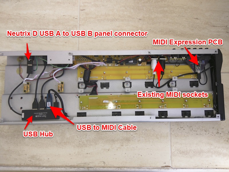
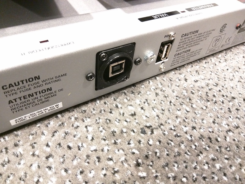
The FCB1010 needs at least 2 cables to make it work, a MIDI out and a mains cable. But for live use I didn’t want either another MIDI cable, or a mains cable added to the snake between keyboard and rack. I would still have needed a 3rd cable for the MIDI Expression. Everything else I have is USB.
I could replace all these switches with the FCB1010 and a sustain pedal - if I could install the MIDI Expression inside the FCB1010. All this would then only need 1 USB cable.
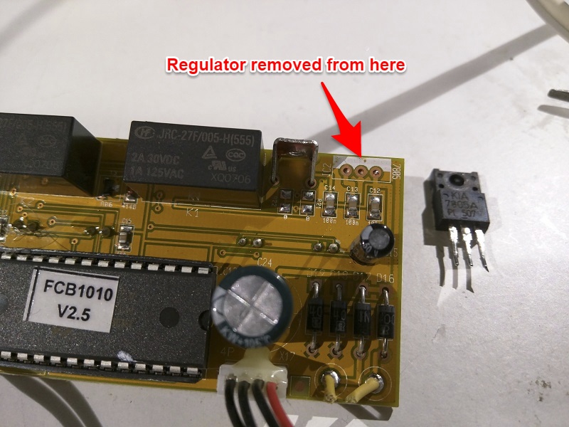
On investigation, the mains power in the FCB1010 goes to a transformer, which converts it to around 10VAC then to a bridge rectifier, and then straight to a 7805 5V regulator. Nothing uses more than 5V, even the output relays are 5V. The current consumption was 90mA at 5V,
So, it was ideal for powering from USB which is 5V.
The plan was to install a 4 port mini USB hub inside the FCB1010. 1 port used to get 5V into the FCB1010, one to go to the MIDI Expression, one for a USB to MIDI converter cable, and a spare one to be extended back to the case so something else could be plugged in if necessary.
Mains socket and transformer removed. Space used for a Neutrik D series reversible USB A to USB B panel socket. I made up a plastic template to mount the socket onto then screwed this into the original holes for the mains socket. The USB panel socket is then reversed so the B socket is presented outside, and the Hub plugged into the A side inside.
All screws and all PCBs removed, with photos taken to get the correct screws back in the correct holes.
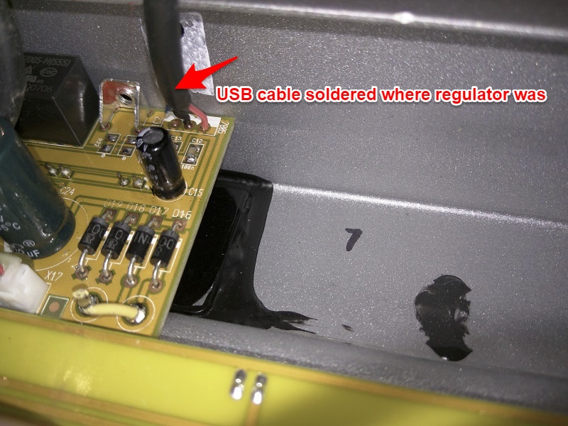
7805 5V regulator removed.
Old USB cable cut in half. I only needed the half with the USB A connector.
Wires stripped from cut end. Removed shield and other wires, just leaving Red and Blackwire.
Black wire soldered to where the centre pin of the 7805 used to go.
Red wire soldered to where the Right Hand Side pin used to go - see photo.
MIDI Expression removed from its case, and front panel containing the 1/4" sockets removed. This is not easy.
Front panel used to mark out cutting lines on back of FCB1010. Without the case, the MIDI Expression JUST fits between the FCB1010 Output sockets, and the edge of the case. Note, The end panel on the FCB1010 needs clearance for a lip and screw which goes inside the case, so you cannot take the Expression or any glue all the way to the edge of the case.
Rectangular opening cut out on the FCB1010 using a drill to start, and an electric jigsaw with a metal cutting blade. I used the jigsaw to nibble away the metal. Note, this creates a lot of metal shavings, which is why it is a good idea to take all the PCBs out 1st, and keep the inside of the FCB1010 as clean as possible. Also I wish I’d put masking tape over the FCB1010 case because I made some marks while maneuvering the jigsaw, despite it having a ruberised protector plate.
Epoxy resined the front panel of the MIDI Expression into the opening. Note. I did try hot glue gun, but it did not stick to the FCB1010 metal. Be very careful not to get glue around the 2 side edges of the MIDI expression front panel, because then the case end panel and OUTPUT sockets won’t fit back in place. I had a plan which was to remove the output sockets from the FCB1010 and to make up a new plastic template for all these sockets.
Re-mounted the MIDI Expression PCB into the newly epoxied front panel. Note - the maker of the MIDI Expression advised to be very careful with the Mico USB connector as it is easy to break it off the PCB. I put some hot glue over it to help strengthen the area.
Drilled hole to mount USB A socket and mounted this where the power switch used to be.
Very clever! Nice piece of DYI - and looks very professional, too!
I still need my FCB 1010 as an old-school MIDI board, so for the time being, it’ll stay as it is, but I’ll definitely save this for my “interesting projects” box!
That’s fantastic, just what I need to do with mine, thank you for sharing. Does it make any difference what version firmware or ROM is in the unit. Mine is a stock pedal with a older firmware.
Firmware shouldn’t make any difference. This is a stock pedal, bought a few weeks ago, and immediately dismantled!
One thing I found during testing this week, the pedal sometimes failed to power up correctly when I used my 5m long USB cables from rack to pedal. It worked fine with shorter cables.
I’ve therefore made an alteration by connecting the USB +5V red cable to the LEFT hand pin where the regulator goes instead of the RIGHT hand side. Then I mounted a small switch into the old grounding screw hole next to the USB socket. The 2 wires from this switch connect to the LEFT hand pin (where the red cable is as well) and the RIGHT hand pin where the regulator went.
This does 2 things. 1. It means you can switch the pedal board on after the USB power has been applied to the hub. 2. It puts an existing 1000uF capacitor in parallel with the power to the FCB board. This helps keep the voltage from sagging while powering up. All works fine after this alteration.
I can take a pic of this altered connection if anyone wants.
I tried a simpler mod and just fitted a 5.5mmx2.1 input socket which I wired to two of the pins of the voltage regulator. This lets me still continuje to power up using mains - or power up by connecting a USB power bank to me new input.
It works fine except for one thing … when I am running on 5v rather than mains the expression pedals do not generate steady CC values - they fluctuate approx +/- 3.
I tried recalibrating the pedals, but this did not help. I do not get this issue when I run using mains power.
That’s a nice simple mod. I like it. What is your battery life with an alkaline or rechargeable pp3? If you use the relay outputs that may reduce the battery life considerably.
One thing to note - if while replacing the battery you inadvertently touch the terminals the wrong way around, then you’ll short circuit the battery through the rectifier diodes. If this is just for a second while trying to connect the battery, then you may be ok with an alkaline battery. If you use a rechargeable, then you’re quite likely to blow those diodes, and then afterwards, the regulator and the electrolytic capacitor.
To avoid this, you might want to put a diode between the centre pin of your socket and the left hand pin of the regulator instead of just a wire. This will prevent any current from flowing if the battery is connected the wrong way around.
Not sure of the battery life yet - still waiting on the battery holder for the single 9v battery. I have used it for about 10 hours so far on a set of 6 AA batteries that were far from new batteries and it’s still going fine. I will report back on that once I’ve flattened my first fresh 9v battery.
As for shorting out, I will be unplugging and unvelcroing the 9v battery each time it gets replaced rather than getting down on my hands and knees and doing it in situ while velcroed to the FCB1010 - so zero chance of a short.
Nice project. I want to do something similar. Can you tell me which MIDI-to-USB cable you used, as the cheap one I bought on eBay does not work? (The resolution on your photo is too low to read the label). Cheers.